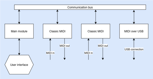
Because audio setups can vary wildly from one person to another I want to make the MIDI router as flexible as possible:
- The number of input/output connections
- The types of electrical interface
There are at least two electrical interfaces I can think of (I don’t have a lot of experience with MIDI):
- The classic MIDI interface, which is a 5-pin DIN connector
- 3.5mm TRS connector
- MIDI over USB
I would like to make at least two types of modules: One for the classic MIDI interface, and one for USB over MIDI. The modules will be able to connect to each other and share MIDI data. Besides these IO modules, there will also be a main module which can be used to set up the routing rules.
The MIDI router allows arbitrary connections to be made between every IO module. Therefore, all modules must have access to all the MIDI information from the other modules. They all need to be connected to each other somehow. Ethernet would be a great way because it has many (somewhat obscure) routing capabilities. However, Ethernet interfaces are complex to set up and each module would require a reasonably capable processor to handle the network stack. It feels like massive overkill for a project like this. We need something simpler and more accessible for the hobbyist.
Shared bus
Using a shared bus which all the modules connect to is the most efficient way to make sure all the modules can talk to each other. But if they all connect to the same interface we need to be careful when to send things over the bus: Two devices cannot talk simultaneously! If this happens, the bus is in contention and communication will not be possible until the other modules are silent. We need a way of preventing this.

Classic gateway
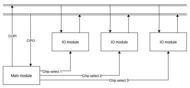
In this scenario, only the main module initiates communication with the IO module. It scans the modules and requests incoming MIDI data, applies the routing rules, and sends the output to the correct module. This avoids bus contention since the main module also functions as the bus arbiter. It determines when modules are allowed to speak, and modules do not speak unless spoken to. SPI (Serial Peripheral Interface) would make a good protocol for this: The transmit and receive lines are shared between all the modules, and an extra ‘chip select’ signal tells the module whether it is allowed to touch the transmit line and whether the main module is talking to it. If the ‘chip select’ is not active for a module, it must let the other modules be able to send ones and zeroes on the transmission line.

While this is arguably the most simple to implement hardware and software wise, it is also highly inefficient. All the processing burden is placed on the main module while most IO modules sit around, waiting to receive information. There is a lot of idle time. Furthermore, depending on the amount of modules there are, the delay between successive communication attempts can get quite large as the main module has to go past each module to ask for new data. This may cause MIDI messages to get delayed and this is unacceptable.
Mesh
To relieve the main module of some processing burden, we can have the modules directly talk to each other. I2C/TWI (Inter-IC Communication / Two Wire Interface) would be a good protocol for this, however a lot of care should be taken to avoid bus contention. The modules will need to figure out when to talk and when to stay silent.

The same issue with message latency is observed as with the SPI protocol. Only a single device can use the bus at the same time, therefore the latency increases with the amount of modules there are.
Ring topology
Woah, that’s a blast from the past! but hear me out. This is a very good idea.
I got inspired by the Ethercat protocol. All devices in an Ethercat setup form a closed loop. Each device has fixed input and output configuration. These configurations are placed in one single frame that goes around and around every device, with each device having access to all the other devices’ data. If a frame gets to a device it replaces its own data in the frame with updated data. Ethercat is widely used in industry and has proven itself.
We can make a simplified form by using serial ports (UART, or universal asynchronous receiver transmitter) which are available on almost any microcontroller. By wiring the transmit pin to the the receive pin of the next module, we can create a daisy chain of modules. The final module wires its transmit pin back to the receive pin of the very first module to complete the loop.

To communicate, the bus master sends out a predefined message in which every device has a place to put its data. It sends this to the first module which starts reading the message and simultaneously transmits it to the next device until it reaches the spot that is reserved for itself: It now sends it’s own data. After that it sends the rest of the incoming data. All the other modules do the same, including the bus master. After the message has completed a full loop, every module now has access to the latest information of all the other devices. This works from the perspective of any device; The message keeps looping forever. Modules can immediately use the information from the previous module in the chain, and only have to wait for a single cycle to get the information from the next module in the chain.
There is no need for bus arbitration: transmission lines are never shared!
>> Home