In the previous post I talked about the communication protocol that I want to use to connect the MIDI IO modules. Usinh Python I have modeled the protocol to see how it functions and if it’s even viable to implement on simple microcontrollers. It seemed like something that could be pulled of without too much effort so I wanted to give it a try on real hardware. An Arduino-like board would be great (and I would probably be able to source them for quite cheap) but I felt like these boards have too much fuz on them: Ideally I just want a bare microcontroller but in a shape that’s easy to breadboard. So I fired up Kicad and made a really simple board that has an Atmega328PB (the refreshed version of the Arduino Uno microcontroller), a crystal, and a programming port. I fanned out all the microcontroller pins to SMT header pins which allows me to stick the unit onto a breadboard.
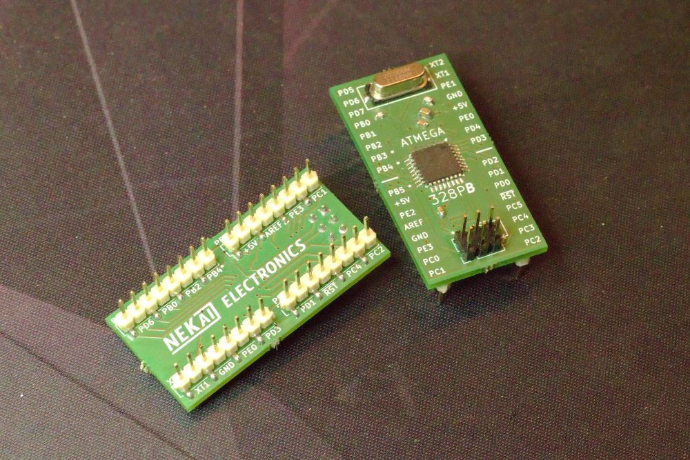
This is almost the bare minimum you need for using a microcontroller: You could skip the crystal and corresponding pair of capacitors if you use the internal 8MHz oscillator! This board has one flaw tho: I made mistake by assuming the 328PB would work with a 20MHz crystal. But it actually only supports crystals up to 16MHz. To get to 20MHz you need a crystal oscillator or a different type of external clock. The boards still work but there are no guarantees about stability (foreshadowing!). I ordered 9 sets, soldered them, and tried them out. “Yup, it’s a microcontroller.” Another dumb mistake I made was ordering too few SMD header pins. Doh.
I will go into more detail about the experiment I ran on these boards in a later post, where I will talk more about the software I’m developing.
MIDI DIN IO module prototype
Before I start developing the real software for these boards I’m gonna need a way to try it out. A way to take some components of the software and try ’em out on the streets, if you will. I also have some kind of idea about how I want these modules to look and function.
- They need a MIDI input and output.
- They need to connect to other modules.
- They need some kind of user interface.
Furthermore, these two things are also important:
- They need to be easy to program.
- Lots of test points.
Choosing the right microcontroller is difficult. There’s many options: Peripherals, program memory size, RAM size, clock speed… I have some kind of idea about the performance I need for this application but I really couldn’t give an estimate. I think the Atmega328PB will do fine and I chose it for this prototype board because it’s widely available, not too expensive and well supported. But I might use a beefier ARM Cortex-M0+ for the next iteration of the board because I’m worried about the relatively low clock speed of the 328.
Here is the schematic I designed: Download schematic-io-mod-proto
Midi input and output

Lets start with the MIDI input and output. The MIDI electrical interface is based on a current loop like the old Telex machines. The loop is ‘idle’ (no current flowing) when the transmitter buffer is at a high signal level (a logical ‘1’). Current starts sinking through the loop into the buffer when it is at a low level. When the current loop is active, the optocoupler in the receiver starts conducting, therefore pulling the input buffer line low. This receiver buffer is also a schmitt trigger which helps clean up the potentially messy signal. It makes a nice clean edge.
Serial ring connection
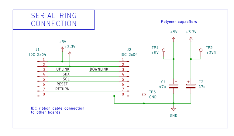
What I’m calling the serial ring connection does not only carry serial data, but also power, the serial return signal (to complete the loop) and an I2C bus for side-channel communication between the main module and the IO modules. This is a convient method of communication when the main module wants to talk to a single module (for example, when configuring said module). This way, the serial ring protocol can stay pretty simple, reducing processing overhead and potential lag in the communication.
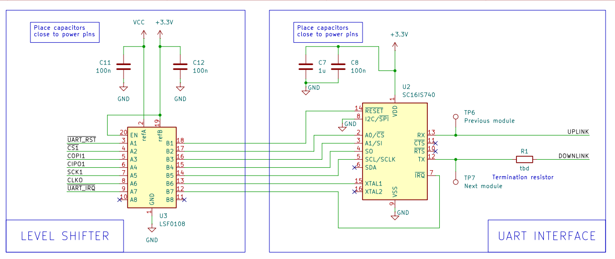
For the actual serial ring communication I opted for a UART chip instead of using the built in serial peripheral of the microcontroller. Why? Because this chip has a buffer of 64 bytes. If the microcontroller happens to not be able to process the serial data quick enough, then this buffer saves me from running the serial ring at a lower rate. It provides a safe zone, which is nice to have in a prototype. A level shifter accompanies this chip.
The microcontroller
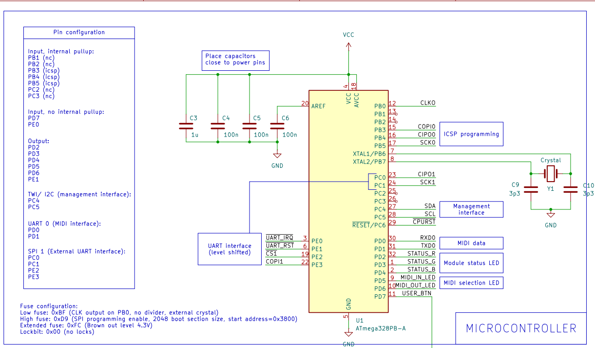
The microcontroller part is not very exciting. It’s a 328PB. I choose SPEEEEEEED and popped in the same 20MHz crystal. Well, that didn’t work out. As soon as I started doing SPI communication on the microcontroller, the oscillator failed reliably. Since I didn’t have any 16MHz crystals, I’m stuck with using the internal 8MHz oscillator until I get some of those. I have also added a full sized AVR ISP programming port. I specifically chose a full size port because it has a keyed connector, and since i’ll probably be doing a lot of reprogramming I want to make sure that I don’t accidentally blow up my board by connecting my programmer in reverse.
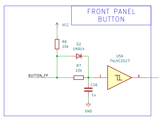
Some LEDs decorate the front panel of the module and this board has probably the most overkill debouncing circuit for a simple push button. But eh, I was looking for an excuse to try out this circuit:
For these modules I’m using boxed header connectors. These can be used with IDC connectors and are keyed, meaning you can’t plug them in the wrong way.
With the schematic finished, I start working on the PCB itself. Stay tuned.
>> Home